

Assumptions
The implementation of the proposed research is based on the following key assumptions:
-
The parking lot features marked and boundary-defined slots, enabling precise mapping between the camera’s predefined coordinates and the actual parking slots.
-
The camera placement ensures a wide field of view that can capture multiple parking slots while maintaining sufficient clarity for license plate detection.
-
The camera should have a minimum resolution of 1080p and support features like auto-focus and HDR (High Dynamic Range) to ensure reliable performance under varying lighting conditions.
-
For outdoor parking lots, IR sensors should be mounted on the ground and placed centrally between the vehicle’s wheels.
-
For indoor parking lots, IR sensors should be fixed on the wall at a height optimal for detecting vehicle presence without obstructions.
These assumptions form the foundation of the system’s accuracy and efficiency, ensuring optimal performance in both indoor and outdoor parking environments.
Schematic overview
The schematic overview of the proposed parking lot is illustrated in Fig. 1. This can represent either closed parking or open parking as per requirement. Every parking slot is equipped with low-cost hardware consisting of an IR sensor, ESP32 (Esp Wroom 32), and a battery as shown. The device can be mounted on the floor, ceiling or wall depending on the parking layout. It ensures real-time tracking with high accuracy while minimizing hardware complexity.

Schematic overview of the proposed integrated model.
Cameras connected with a Raspberry Pi can oversee multiple parking slots at a time, significantly reducing the need for expensive, dedicated setups. The camera captures the parking area in addition to IR sensors placed within each slot to confirm vehicle presence, enhancing detection reliability. Data from IR sensors is communicated via Esp Wroom 32 to the Raspberry Pi microcontroller to update the parking slot occupancy in real time. This low-cost, adaptable framework is suitable for both indoor and outdoor environments, addressing challenges like accurate detection, occupancy tracking, and cost optimization.
The proposed research consists of the following modules:
-
Vehicle recognition system (VRS) at the entrance and exit: The vehicle recognition system (VRS) at entry allows the vehicles to enter inside depending on the availability of the free slots inside the lot. The authors of5 have suggested an automatic gate open system of the parking lot concerning the availability of the parking slot inside. In the current work, the camera at the entry and exit points in Fig. 1 records the license plate and the time of entry or exit to measure the parking duration. The Raspberry Pi(s) inside the parking lot work as the edge devices and are used to inform the display at the entry about the number of empty slots and accordingly vehicles are allowed inside. Similarly, the camera at the exit will detect the vehicle leaving the lot and update the database accordingly.
-
Vehicle parking detection system (VPDS): The vehicle parking detection system (VPDS) shown in Fig. 2 uses an IR sensor along with an ESP32 module and battery at each slot for vehicle detection. Upon arrival of a vehicle inside the parking slot, the IR sensor detects it and the state is communicated to the Raspberry Pi via the ESP32 microcontroller. Four nos of cameras are connected to the microcontroller (Raspberry Pi 4 Model B) by using the USB and the Pi slot to capture multiple vehicles at a time. By using an appropriate computer vision-based algorithm, multiple vehicles in different frames will be captured and the license plates will be detected. Slot-coordinate matching ensures accurate parking assignment, with dual verification from IR sensors to enhance detection accuracy while reducing hardware costs.
As experimented in Fig. 3 multiple vehicles have been captured by using one Pi camera and one USB camera connected to the Raspberry Pi 4 Model B microcontroller. The details of the license plate extraction by the slot and frame matching algorithm are explained later in this article.
-
Smart metering display (SMD) unit: The smart metering display (SMD) unit at the exit in Fig. 1 measures the occupancy duration using data from IR sensors and the camera. Fare details are displayed for customer convenience, supporting the revenue generation of the parking operators. When the IR sensor detects a vehicle in the defined range, it captures the license plate and matches the vehicle number read with the database. It fetches the total Fare stored in the database and displays it at the exit upon finding the match. At the same time, the slot counter is decremented by one for occupied slots and incremented by one for available slots.

Architecture of the vehicle parking detection system (VPDS).

Experimental setup for a Raspberry Pi 4 Model B with Pi camera and USB camera.
Proposed methodology
An overall architecture of the VPDS and multiple license plate recognition through a single capture at the edge layer is depicted in Fig. 4.

Proposed system architecture for vehicle detection and monitoring setup.
When the vehicle enters the parking lot through the Entry gate as shown in Fig. 1, it is detected by the IR sensor at the entry gate which activates the camera in return. The camera then captures the vehicle’s license plate as per the procedure represented in Fig. 5.

Pseudo code for working of the vehicle recognition system.
As the vehicle is recognised by the camera, the parking duration measurement starts for the vehicle. A similar algorithm is executed at the exit gate to know the exit of the vehicle. Advanced image processing techniques are then applied to the captured image to detect the vehicle’s frame and identify its colour. Using Gaussian Blurring and Thresholding, noise is reduced and the image is segmented for clear vehicle boundaries. Following this, contouring is used to localize and draw a bounding box around the license plate. Once the vehicle’s frame and license plate are isolated, Optical Character Recognition (OCR) is employed to extract the license plate text from the bounding box.
-
YOLO detects parked vehicles, matching their coordinates with slot data. Verified occupancy triggers license plate capture and cross-referencing with the database to start the timer and fare calculation.
-
The slot counter updates automatically, displaying availability at the parking entry.
-
Upon exit, metering stops, and the fare and vehicle details are stored in the database for billing and records.
When a parked vehicle is detected by the camera, the system cross-references the detected coordinates with predefined parking slot locations, verifying occupancy. After successful verification, the license plate of the vehicle is captured using Optical Character Recognition (OCR) and matched with the vehicle database, enabling accurate vehicle tracking and automated fare calculation.

Images in different positions of the Sun by the USB camera connected to Raspberry Pi.
Figure 6 shows the experimental images captured by the USB camera in two opposite parking lanes, one facing towards the sun and the other in the opposite direction of the sun. The novelty of the research lies in extracting license plates of individual vehicles from a single frame. It can be understood that the Raspberry Pi microcontroller while connected to four different cameras at the time can capture a total of four images having multiple slots in each image. By using a USB camera in the experiment, one frame can capture 5 parking slots as shown in Fig. 7.

Image captured in USB camera facing towards sun.
Therefore, depending on the positioning of the camera and the wide angle used by the camera, multiple parking slots can be captured in one frame and the same extraction algorithm can be used for license plate recognition.
The following presents the pseudo-codes for matching vehicle coordinates with parking slots (Fig. 8), validating the detected vehicle with IR sensors (Fig. 9) and the corresponding database updation (Fig. 10):
-
Vehicle and parking slot coordinates matching:
-
Slot coordinates and unique IR ID matching:
-
Database Updation Methodology:

Vehicle coordinates matching algorithm.

Vehicle validation with IR sensors.

Database updation for slot occupancy and fare calculation.
Vehicle identification from the camera feed
Gaussian Blurring is applied to minimize noise and smooth the camera image. The process of vehicle identification from the camera feed begins with analysing the video feed and using the Gaussian blurring technique focusing on a threshold value of vehicles and license plates based on the still image contrast. The result of applying this technique is depicted in Fig. 11.

Background noise reduced using Gaussian Blurring technique in the proposed integrated model.
A grid-based detection approach is applied which identifies the vehicle by placing an abounding box around it and then isolating the license plate with a secondary boundary box specifying its exact coordinates. This dual detection method ensures the precise identification of vehicles for subsequent processing. The result is shown in Fig. 12

Vehicle and license plate identification with bounding boxes in the proposed model.
Gaussian blurring technique
In this proposed work, Gaussian blurring is applied to the HSV (Hue, Saturation, Value) image to reduce noise and smoothen the image. This is achieved by convolving the image with a Gaussian kernel. From the study explained thoroughly in Kostková et al.7 mathematically, the Gaussian blur operation can be represented as:
$$\beginaligned G(x, y) = \frac12\pi \sigma ^2 \cdot e^-\fracx^2 + y^22\sigma ^2 \endaligned$$
(1)
where:
-
1.
\(G(x, y)\) is the Gaussian kernel at position \((x, y)\).
-
2.
\(\sigma\) is the standard deviation of the Gaussian distribution.
-
3.
\(e\) is the base of the natural logarithm.
The Gaussian blur operation is performed by averaging the pixels in the vicinity of each pixel, giving more weight to the central pixels. This effectively reduces high-frequency noise in the image.
In the proposed implementation, the technique is applied to the HSV image using a kernel size of \((11, 11)\) and a standard deviation of 0, as shown in Fig. 11. Adjusting the kernel size or the standard deviation can alter the blurring effect. Smaller kernel sizes or more minor standard deviations produce lighter blurs, while larger values create stronger blurs.
Thresholding
Thresholding is a fundamental image processing technique that converts grayscale images into binary ones by categorizing pixels as either black (0) or white (255) based on a predetermined threshold value. From a study explained thoroughly—mathematically, the thresholding operation can be represented as:
$$\beginaligned \text Binary(x, y) = {\left\ \beginarrayll 1, & \text if \text Gray(x, y) > \text Threshold \\ 0, & \text otherwise \endarray\right. \endaligned$$
(2)
where:
-
1.
\(\text Binary(x, y)\) represents the binary output image at position \((x, y)\).
-
2.
\(\text Gray(x, y)\) is the grayscale value of the input image at position \((x, y)\).
-
3.
\(\text Threshold\) is the predefined threshold value.
Here, thresholding is applied after converting the frame to the HSV colour space. The ‘cv2.inRange()’ function creates a binary mask by isolating specific colours within the specified range defined by ‘lower_color’ and ‘upper_color’. This binary mask aids in identifying edges through subsequent contour detection using the Canny edge detection algorithm (‘cv2.Canny()’).
YOLO (You Only Look Once) method
YOLO is an advanced, grid-based object detection algorithm known for its speed and accuracy in detecting and localizing objects within an image. In this proposed model, YOLO is utilized to detect both the vehicle boundary and the license plate within the processed image, which has undergone preliminary enhancement techniques, such as Gaussian Blurring and Thresholding.
In YOLO, the input image is divided into an \(S \times S\) grid, where each grid cell is responsible for predicting bounding boxes and class probabilities for the objects within it. Given an input frame, YOLO processes the entire image at once, predicting bounding boxes and their associated confidence scores in a single pass through the network.
The mathematical approach for YOLO detection can be described as follows:
-
1.
Bounding box prediction: Each grid cell predicts \(B\) bounding boxes. A bounding box is defined by four parameters \((x, y, w, h)\):
-
(a)
\((x, y)\): The coordinates representing the center of the bounding box.
-
(b)
\(w\): The width of the bounding box relative to the entire image.
-
(c)
\(h\): The height of the bounding box relative to the entire image.
-
(a)
-
2.
Confidence score: Each bounding box has an associated confidence score that reflects the likelihood of containing an object and the accuracy of the bounding box coordinates:
$$\beginaligned \text Confidence Score = P(\text object) \times \text IOU_\text pred^\text truth \endaligned$$
(3)
where \(P(\text object)\) is the probability of an object being in the bounding box, and \(\text IOU_\text pred^\text truth\) is the Intersection over Union between the predicted bounding box and the ground truth.
-
3.
Class prediction: Each grid cell also predicts \(C\) class probabilities for the presence of an object within the cell:
$$\beginaligned \text Class Probability = P(\text class | \text object) \endaligned$$
(4)
YOLO calculates the final score for each bounding box by multiplying the confidence score with the class probabilities.
In this work, YOLO first identifies a bounding box around the vehicle boundary, marking this area as the Region of Interest (ROI) for the next detection stage. The algorithm then re-evaluates the ROI for a finer license plate detection, creating a nested bounding box within the vehicle boundary as shown in Fig. 12. This dual-stage detection allows for targeted processing, ensuring that only relevant portions of the frame are considered, reducing unnecessary computation and enhancing accuracy.
The mathematical representation of this grid-based approach is:
$$\beginaligned \text Output(i, j) = {\left\ \text object)), & \text if object detected in grid cell \\ 0, & \text otherwise \endarray\right. \endaligned$$
(5)
where \((i, j)\) represents a specific grid cell.
After identifying the vehicle boundary with a bounding box, a nested bounding box is drawn within it, targeting the license plate based on additional YOLO predictions focused within the ROI. This hierarchical detection technique, combined with earlier pre-processing steps (Thresholding, Gaussian Blurring, etc.), produces robust results in detecting both the vehicle and its license plate, facilitating further stages like Optical Character Recognition (OCR) for license plate text extraction.
License plate recognition
A study by Du et al.21 reviews Automatic License Plate Recognition (ALPR) technology, outlining its applications, operational principles, and challenges. It categorizes ALPR techniques based on features used and compares them regarding accuracy and inference. However, it lacks detailed discussions on limitations and recent advancements and could benefit from practical examples to illustrate effectiveness.
This model overcomes these shortcomings in traditional ALPR techniques by effectively handling diverse environmental conditions, accommodating license plates from different regions, enhancing image quality, and enabling real-time processing.
This section covers the crucial step of extracting text information from images using Optical Character Recognition (OCR). The captured image is processed using Grayscale Conversion and Noise Reduction techniques to enhance the text. The OCR software (Tesseract) recognises and extracts the text. Tesseract analyzes the image, identifies character patterns, and converts them into machine-readable text.
Gray scale conversion
Converting to a grayscale image is very important in pre-processing the images before they are analyzed or used in computer vision. This entails changing an image’s initial colour representation. Usually, RGB (red, green, and blue) is used in grayscale, where each pixel value reflects brightness or luminance. From the study explained thoroughly in Saravanan et al.22 mathematically, it can be expressed as:
$$\beginaligned Y = 0.299 \times R + 0.587 \times G + 0.114 \times B \endaligned$$
(6)
where:
-
1.
\(R, G, B\) represent red, green and blue colour planes for the original image.
-
2.
\(Y\) denotes the resulting intensity value in grayscale.
In the case of text extraction, converting images into grayscale simplifies them to the extent that one channel does not retain any essential information required by text but has reduced computational load, which can be understood from Fig. 13. By expressing an image using its intensity values, grayscale conversion brings out more vivid details concerning texts and contrasts, making it easier to see words against other parts of a document. This makes things simple for subsequent algorithms to recognize such texts because instead of dealing with each transition’s changes in intensity related to each character’s font style.

Grayscale conversion of an RGB image for text extraction.
Noise reduction
Noise in images means random changes in pixel values, which may lead to poor image quality and disrupt text extraction accuracy. Reducing noise is essential because it helps to reveal details hidden within an image. One of the most frequently employed methods for reducing noise is Gaussian Blur, a spatial filter that smooths the image by minimizing the effect of high-frequency noise.
In simple terms, Gaussian Blur works by summing weighted averages for each pixel based on values obtained through a Gaussian function surrounding a given pixel. This operation can be written as:
$$\beginaligned \text Blur(x, y) = \sum _i=-k^k \sum _j=-k^k \text Pixel(x+i, y+j) \cdot \text Kernel(i, j) \endaligned$$
(7)
where:
-
1.
\(\text Blur(x, y)\), is the resulting intensity value at (x,y).
-
2.
\(\text Pixel(x+i, y+j)\), indicates the intensity value of neighbouring pixels relative to an offset (i,j).
-
3.
\(K(i,j)\), represents the coefficient of Gaussian kernel at position (i,j).
-
4.
k stands for kernel size.
The process significantly removes high-frequency noise while preserving vital features like edges and text, thus smoothing the image. The result is reduced noise level and improved clarity, making extracting meaningful text more precisely easier, as shown in Fig. 14. Gaussian Blur is a fundamental noise reduction technique that plays a crucial role in enhancing the accuracy of text extraction algorithms by mitigating the impact of noise in the input image.

Reducing noise by subtracting the background and reducing the image size, emphasising the License Plate.
Tesseract
Tesseract, an open-source Optical Character Recognition (OCR) engine developed by Google, employs advanced algorithms to extract text from images. Its functionality can be mathematically represented as:
$$\beginaligned \text Text(x, y) = \text Tesseract(I(x, y)) \endaligned$$
(8)
where:
-
1.
\(\text Text(x, y)\) represents the recognized text at position \((x, y)\) in the image.
-
2.
\(I(x, y)\) denotes the intensity or pixel value at position \((x, y)\) in the input image.
Tesseract analyzes the structural features of text within the image, recognizing patterns and converting them into machine-readable text. This process involves sophisticated pattern recognition algorithms that discern text elements from background noise and other visual distractions.

Individual character recognition by creating bounding boxes separately around each character.
Due to its robust design, Tesseract can accurately detect and extract text from images with complex backgrounds or distortion, as shown in Fig. 15. Its versatility and reliability make it a valuable tool for various text recognition applications, from document scanning to image-based data extraction in various industries.
Smart metering
Smart metering is the process of measuring the parking duration of a vehicle from its entry to the exit. The fare calculation system is designed to compute charges based on the vehicle’s occupancy duration in the parking slot. The formula used is:
$$\beginaligned \text Total \ \text Fare = \text Occupancy\ \text Duration * \text Cost\ \text per\ \text Second \endaligned$$
(9)
Occupancy duration is recorded with accurate timestamps captured through sensor and image processing technologies. The cost per second is a predefined rate used to compute the total charges automatically. The system supports a dynamic pricing structure that adjusts rates based on peak and off-peak hours to enhance efficiency, which is displayed on the smart metering device (Fig. 16). This ensures fair billing while optimizing resource usage. By automating the fare calculation process, the system minimizes human error, providing a reliable and scalable billing solution to the parking operator.

Smart metering device displaying the total fare at parking exit.
Database integration
The integration of a centralized database system, implemented using Microsoft SQL Server Management Studio (SSMS) and SQLite, enhances the efficiency and reliability of the proposed parking management system as shown in Fig. 17. The database is designed to store critical information such as vehicle details, slot coordinates, IR sensor IDs, occupancy status, and fare calculation data. This robust setup ensures seamless data storage, retrieval, and management, supporting the system’s core functionalities.
Key features of database integration include:
-
Slot and vehicle matching: The database facilitates the precise association of detected vehicles with predefined slot coordinates as shown in Fig. 18 using a combination of YOLO-based detection and IR sensor ID confirmation. When the column values of D and E match, the parking of a vehicle is verified.
-
Real-Time Slot Monitoring: The system continuously updates the occupancy status of parking slots, providing real-time data for slot availability displayed at the entrance. This reduces congestion and optimizes parking space utilization.
-
Fare Calculation: Occupancy duration and dynamic pricing details are stored in the database, enabling automated, accurate billing. Each vehicle’s parking history and fare details are maintained for record-keeping and audit purposes.
-
Admin Operations: Administrators can use SSMS to interact with the database, updating or retrieving data as needed. This simplifies operations such as adjusting pricing models, tracking resource usage, and managing slot assignments.
The integration of SSMS also strengthens data security and ensures that the system can scale to accommodate larger parking lots or advanced features like predictive analytics and customized user preferences. By consolidating key functionalities into a centralized database, the system ensures smooth operations, enhances resource allocation, and provides a seamless parking experience for both administrators and users.

Database of Parking with 50 Test slots with a unique SlotID dedicated to each slot and slots counter for the number of available and occupied parking slots.
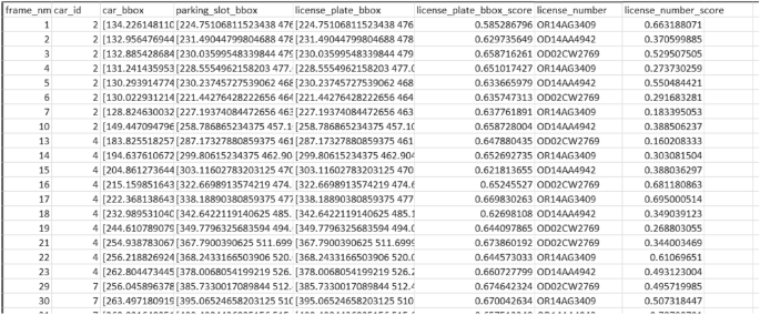
Exported CSV file of the processed database.
link